Ceiling Radiation Damper Cad Detail

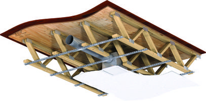
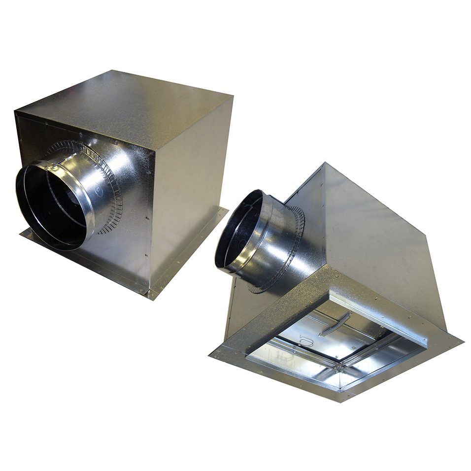
The connection of the ceiling radiation damper diffuser neck and steel duct drop see connection notes section on page 3 may be satisfied in three ways.
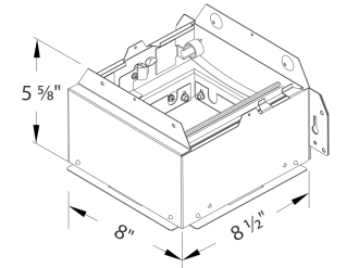
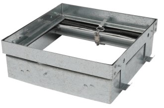
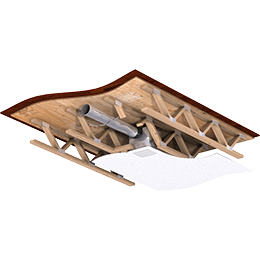
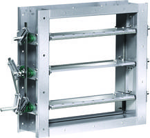
Ceiling radiation damper cad detail. Damper is supported directly by the grid system and may lay on top of perforated metal or similar grille core material fusible link support wire must attach to duct or ceiling supports above. The ceiling damper may be connected directly to the grille and supported by steel channel see figure 6 detail g. Opening in ceiling membrane see page 1 may be up to 1 25mm larger than the nominal size of the ceiling radiation damper i e. Cad drawings dwg.
Fire and heat protection where hvac components penetrate the ceiling membrane. The cfd2 is a ul555c classified ceiling fire damper. Ceiling radiation damper any be connected directly to the air device neck and then the duct drop connected to the damper see detail b figure 6. Ceiling radiation damper and air device neck may be connected directly to the duct drop see detail a figure 6.
Ul rated fire smoke and ceiling radiation dampers.


